
ACCOLADE ESTATE
DESIGN, INSTALLATION AND SERVICING INSTRUCTIONS
For Gledhill Accolade Estate Parts and Spares click on the following links: Gledhill Accolade Estate Parts And Spares
PLEASE LEAVE THESE INSTRUCTIONS ADJACENT TO THE CYLINDER

An unvented hot water storage unit complying with the requirements of Building Regulations Approved Document G3.
Please read these instructions before commencing installation.
in the interest of continuously improving the Accolade Estate range, Gledhill Water Storage Ltd reserve the right to modify the product without notice, and in these circumstances this booklet, which is accurate at the time of printing, should be disregarded
Table of Content
ISSUE 6 : 06-08
|
Sl
|
Section | Page |
| 01 | Description | 3-4 |
| 02 | System Design | 5-7 |
| 03 | Installation | 8-14 |
| 04 | Commissioning | 15 |
| 05 | Servicing/Maintenance | 15 |
| 06 | Fault Finding | 16 |
| 07 | Parts | 17 |
| 08 | Terms & Conditions | 19 |
These instructions should be read in conjunction with the installation/servicing instructions issued by the manufacturer of the heat source being used. Any installation must be in accordance with the relevant requirements of the Gas Safety Regulations, Local Building Regulations, I.E.E. Wiring Regulations and Byelaws of the Local Water Undertaking. It should be read in accordance with the relevant recommendations of the following:
BS 6798; BS 5549; BS 5546;
BS 5440:1; BS 5440:2; CP 331:3
BS 6700: BS 5258 and BS 7593: 1992
It must be installed by a competent person as defined by part G3 of the Building Regulations. Manufacturers notes must NOT be taken as over-riding statutory obligations.
Accolade Estate is covered by Section G3 of the Building Regulations and is therefore notifiable to Building Control.
This information is provided to assist generally in the selection of equipment.
Responsibility for selection and specification of our equipment must however remain that of our customer and any experts or consultants concerned with the installation(s).
PLEASE NOTE: THAT WE DO NOT THEREFORE ACCEPT ANY RESPONSIBILITY FOR MATTERS OF DESIGN SELECTION OR SPECIFICATION, FOR THE EFFECTIVENESS OF AN INSTALLATION OR SYSTEM CONTAINING ONE OF OUR PRODUCTS UNLESS SPECIFICALLY REQUESTED TO DO SO IN WRITING.
All goods are sold subject to our Conditions of Sale which are set out at the rear of this specification. In the interest of continuously improving the Accolade Estate range, Gledhill Water Storage Limited reserve the right to modify the product without notice, and in these circumstances this booklet, which is accurate at the time of printing, should be disregarded. An updated set of Instructions will be produced and supplied with new appliances and will be made available for other appliances on request.
A KIWA PRODUCT APPROVED TO COMPLY WITH ALL RELEVANT PARTS OF THE BUILDING REGULATIONS AND WATER SUPPLY (WATER FITTINGS) REGULATIONS.
ACCOLADE ESTATE IS PRODUCED UNDER AN ISO 9001:2000 QUALITY SYSTEM APPROVED BY BSI.

As part of the undustry wide “Benchmark” Initiative all Gledhill Accolade Estates now include a Benchmark Installation, Commissioning and Service Record Log Book. Please read carefully and complete all sections relevant to the appliance installation. The details of the Log Book will be required in the event of any warranty work being required. There is also a section to be completed after each regular service visit. The completed Log Book and these instructions should be left with the cylinder in the pocket provided.
DESCRIPTION
For Gledhill Accolade Estate Parts and Spares click on the following links: Gledhill Accolade Estate Parts And Spares
MANUFACTURER GLEDHILL WATER STORAGE LTD
| Maximum inlet pressure to Pressure Reducing Valve | 6 bar |
| Operating pressure (PRV setting) | 1.5 bar |
| Expansion Relief Valve setting | 3 bar |
| Maximum primary working pressure | 3.5 bar |
| Opening pressure of T & P Relief Valve | 4 bar |
| Opening temperature of T & P Relief Valve | 90ºC |
| Energy cut-out thermostat setting | 80ºC |
| Immersion heater: Redring Type GU | 11TC |
| Rating: 3kW, 240V AC | |
| Drain tap will empty 100% of contents |
All cylinders are manufactured in accordance with the requirements of BS7206 : 1990.
The tundish must be positioned so that it is visible to the occupant and is away from electrical devices.
Components supplied with Accolade Estate:
Expansion relief/PRV combination valve
Temperature and Pressure Relief Valve
Control thermostat
Energy cut-out thermostat
Energy cut-out motorised valve (indirects only)
Tundish
Immersion heater
(Note: Two immersion heaters are supplied with the direct Accolade Estate)
In any situation where the volume of heated pipework (eg. secondary circulation pipes or manifold pipework for multiple units) exceeds 10 litres, then an additional expansion vessel must be fitted to accommodate the extra expansion volume.
HANDLING BEFORE INSTALLATION
Accolade Estate must be handled with care and stored the correct way up in a dry place. Any manual handling/lifting operations will need to comply with the requirements of the Manual Handling Operations Regulations issued by the H.S.E.
The appliance can be moved using a sack truck on the rear face although care should be taken and the route should be even.
In apartment buildings containing a number of storeys we would recommend that the appliances are moved vertically in a mechanical lift.
If it is proposed to use a crane expert advice should be obtained regarding the need for slings, lifting beams etc.
A specific manual handling assessment is shown in Appendix B at the rear of this manual.
MAINTENANCE
For Gledhill Accolade Estate Parts and Spares click on the following links: Gledhill Accolade Estate Parts And Spares
Modifications should not be made to this product. Replacement parts, including immersion heaters, should be purchased from Gledhill Water Storage Limited, or agents approved by them.
Unvented hot water storage vessels need regular routine checks, and these are detailed below. It is for this reason that this manual must always be left with the Accolade Estate.
It is recommended that these checks be carried out at the time of boiler maintenance by a qualified installer:
1. Manually open the relief valves in turn, and check that water is discharged from the valves and runs freely through the tundish and out at the discharge point. Ensure that the valves re-seat satisfactorily.
2. Turn the mains water off and remove and clean the strainer element in the Pressure Reducing Valve.
3. Check the charge pressure in the expansion vessel and repressurise if required
4. Re-fill the system and ensure that all relief valves have re-seated.
DESCRIPTION
INTRODUCTION
Accolade Estate is a range of unvented hot water storage appliances designed to provide mains pressure hot water to comply with Section G3 of the Building Regulations. The Accolade Estate incorporates a twin tank design and is housed in a pre-finished rectangular case with all connections front mounted. The appliance is extremely well insulated using high density HCFC free foam insulation with an ozone depleting potential (ODP) of zero. It is fitted with all necessary safety devices and supplied with all the necessary control devices to make installation on site as easy as possible.

The twin tank configuration is important in ensuring more usable water because the pipework is arranged so that gravity circulation takes place constantly around two tubes. In a single tube cylinder some 15% of the contents, which are below the heat exchanger, remain unheated, and therefore at an unusable temperature. The twin tube design of Accolade Estate overcomes this problem and therefore significantly reduces the risk of legionella. Drain down is effected from the very bottom of both tubes.
Accolade Estate is available in two basic variants:
1. Accolade Estate Direct - For providing hot water heated by electricity (Figure 1).
2. Accolade Estate Indirect - For use with gas or oil boilers (Figure 2).
ACCOLADE ESTATE DIRECT (Figure 1) Accolade Estate direct is an electrically heated, unvented hot water storage package appliance designed primarily for use with off peak electrical supplies.
It is supplied fitted with two 3kW immersion heaters as recommended by the Electricity Council and BEAB approved for safety.
Accolade Estate direct models are listed in Table 1.

ACCOLADE ESTATE INDIRECT (Figure 2)
Accolade Estate indirect is an unvented hot water storage package and is provided with an internal coil which is designed for use with a gas or oil boiler and is suitable for both open vented and sealed pumped primary systems.
When used with a sealed heating system the boiler must incorporate its own energy cut-out overheat thermostat.
Accolade Estate indirect models are listed in Table 2.
SYSTEM DESIGN
 ACCOLADE ESTATE DIRECT
Basic Appliance - see Figure 1
1. Anti vacuum valve
2. Temperature and Pressure relief valve
3. 1¾” x 3kW on peak (boost) upper immersion heater (incalloy) complete with control and overheat thermostats
4. 1¾” x 3kW off peak lower immersion heater (incalloy) complete with control and overheat thermostats
5. ½” BSP (M) - for connection to the potable expansion vessel
6. 22 mm copper - for connection to the 1½ bar cold feed from the combination inlet group
7. ½”BSP (F) connection - for drain valve (not supplied)
8. 22 mm copper - connection for hot water supply
Component kit supplied separately:-
1. Combination valve incorporating pressure reducing valve, strainer, cold water connections, expansion relief valve and check valve.
2. Potable water expansion vessel.
3. Tundish.
4. Installation instructions.

SYSTEM DESIGN

ACCOLADE ESTATE INDIRECT
Basic Appliance - see Figure 2
1. Anti vacuum valve
2. Temperature and Pressure relief valve
3. 1¾” x 3kW emergency immersion heater (incalloy) complete with control and overheat thermostat
4. 22 mm copper - for connection to the primary return.
5. ½”BSP (M) for connection to the potable expansion vessel
6. Pocket for control/high limit thermostat
7. 22 mm copper - for connection to the primary flow
8. 22 mm copper - for connection to the 1½ bar cold water feed from the combination inlet group
9. ½” BSP (F) connection for drain valve (not supplied)
10. 22 mm copper - connection for hot water supply
Component kit supplied separately:-
1. Combination valve incorporating pressure reducing valve, strainer, cold water connections, expansion relief valve and check valve.
2. Potable water expansion vessel.
3. Tundish.
4. 2 port motorised valve.
5. Control/overheat thermostat.
6. Installation instructions.
(1) Heating from cold 15ºC to 65ºC of total storage volume
(2) Heating from 15 ºC to 60ºC after 70% volume has been drawn off
(3) Full boiler power used to heat water from 15ºC to 60ºC
If you require an open vented model please add OV to the model size - or SS for a sealed system
SYSTEM DESIGN

INSTALLATION
For Gledhill Accolade Estate Parts and Spares click on the following links: Gledhill Accolade Estate Parts And Spares
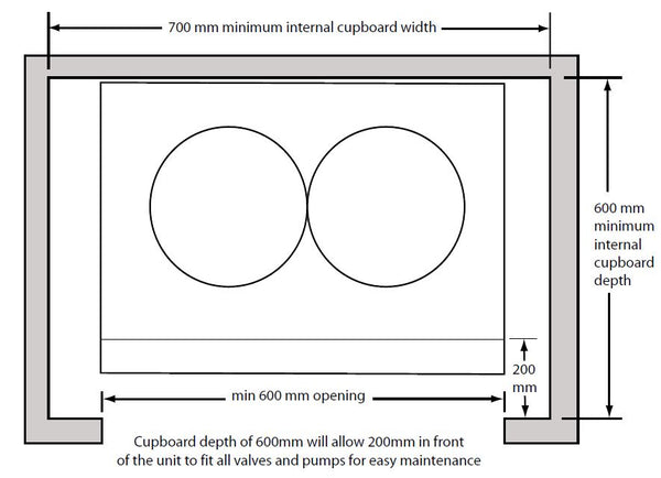
GENERAL DESIGN CONSIDERATIONS
The minimum cupboard width t o accommodate the Accolade Estate is 700mm.
The base chosen for the cylinder should be level and capable of supporting the weight of the unit when full of water as shown in General Data. The discharge pipework for the safety valves must have a minimum fall of 1 : 200 from the unit to a safe discharge point. All exposed pipework should be insulated and the unit should NOT be fixed in a location where the contents could freeze.
The pipe connecting the boiler flow to the appliance must not be less than 22mm copper or equivalent.
There should be no valves or other equipment in the pipe connecting the boiler flow to the appliance.
MAINS WATER SUPPLY
Existing properties with a 15mm supply will be satisfactory provided the local mains pressure is good, but should be confined to single bathroom properties. For new properties where simultaneous demand is required to more than one bathroom or a bathroom and one or more en-suites, the communication and service pipe into the dwelling should be a minimum of 22mm (usually in the form of a 25mm MDPE supply). The minimum recommended static pressure to operate an Accolade Estate domestic system is 2 bar. There should be a flow of at least 25 litres per minute or above available into the property. Normally Accolade Estate provides well in excess of 30 litres/min in most conditions. Flow rates for ALL mains pressure systems are subject to district pressures and system dynamic loss.

If two Accolade Estates are coupled together the secondary inlet and outlet pipes must be balanced. The units must be fitted on the same level.
GENERAL RESTRICTIONS
a. The highest hot or cold water draw off point should not exceed 4 metres above the Pressure Reducing Valve.
b. An ascending spray type bidet or any other appliance with a Class 1 back-syphonage risk requiring a type A air gap should not be used.
c. Accolade Estate should not be used where steam is the primary heating medium, or in a situation where maintenance is likely to be neglected.
d. Unvented cylinders are not suitable for use with solid fuel boilers.
INSTALLATION
e. If the supply to the mixer fittings (other than a dual outlet type) is not taken
from the balanced supply the system will become over pressurized and cause
the pressure relief valve to discharge. Over time this could also cause the
premature failure of the appliance itself which will not be covered by the
warranty,
f. I n larger properties with a number of bathrooms/en-suites and long pipe runs we would recommend that the balance cold supply is provided with its own pressure reducing valve and is not taken from the balanced cold connection on the combination valve. In this case it will also be necessary to fit a small expansion vessel on the balanced cold water system to accommodate the pressure rise caused by the increase in temperature of the balanced cold water.
SHOWER FITTINGS
Any type of shower mixing valve can be used as long as both the hot and cold supplies are mains fed. However, PRESSURE COMPENSATING shower mixing valves are proven to give better control when more than one fitting are open simultaneously and are therefore STRONGLY RECOMMENDED. Thermostatic versions are preferable.
PIPE LAYOUT
In all mains pressure installations it is important to remember that the incoming cold supply must be shared between all terminal fittings. It is important that a 22 mm supply is brought to the appliance and a 22mm take-off is continued at least to the bath. If there are two baths, 28mm pipework should be considered. Smaller pipework, or the use of flow restrictors, should be considered for other outlets so as to balance the water available. In any event the distribution pipework should generally be in accordance with BS6700.
PLASTIC PIPEWORK
This appliance is suitable for use with plastic pipework as long as the material is recommended for the purpose by the manufacturer and is installed fully in accordance with their recommendations.
SECONDARY HOT WATER CIRCULATION
The two largest indirect models are fitted with a secondary return tapping as standard. This tapping may also be fitted on other models on request. If fitted, an extra expansion vessel may be necessary. A non-return valve MUST be FITTED near the return connection. No valve or terminal fitting should be installed between the non return valve and the cylinder.

Note:
Cold supplies to single taps taken from the mains cold water system
Cold supplies to mixer taps to be taken from the balanced cold water connection on the combination valve
INSTALLATION
PRESSURE & TEMPERATURE RELIEF PIPEWORK
The safety relief valves should be installed to discharge in accordance with G3 of the Approved Document of the Building Regulations and should be piped to where it is visible, but will not cause danger to persons or damage to materials.
The discharge pipework should be of metal and from the tundish should fall vertically for at least 300mm, and then continue by continuous fall to a visible safe termination. The discharge termination point should be below a fixed grating and above the water seal of a trapped gully or other permissible terminations as in G3 of the Approved Document. Discharges should be visible at either the tundish or the termination.
Typical Discharge Pipe Arrangement

SAFETY
The safety devices supplied or fitted on an Accolade Estate are selected for their suitability for the temperatures and pressures involved. They must not be changed or removed and it is essential that replacements must be supplied or approved by Gledhill Water Storage Limited. This includes the immersion heaters, which must incorporate energy cut-out, and are available to approved installers from Gledhill Water Storage Limited, Sycamore Estate, Squires Gate, Blackpool (Telephone 01253 474402).
COMBINATION INLET GROUP
Combines elements 1, 2 and 3 below.
1. Pressure Reducing Valve - This must be fixed near the cylinder. The cold water supply terminal fittings in the property should be taken from the cold water tapping of this valve to ensure balanced hot and cold pressures. This valve is factory set to ensure the correct operating pressure for the Accolade Estate.
2. Non Return Valve - This is integral with the pressure reducing valve to prevent backflow of hot water towards cold water draw off points.
3. Cold Water Expansion Relief Valve - This safety device is preset at the factory and will relieve excess cold water pressure resulting from a fault condition.

Locations to be avoided when siting a discharge pipe at high level:
1. The discharge pipe should not be located above a pedestrian area, or above a window, door, ventilator etc.
2. Subsequent freezing of the discharge should not create a hazard to persons about the building.
3. The adjacent structure should be impervious to water at 80ºC.
Alternative Discharge Arrangement (High Level)
INSTALLATION

TEMPERATURE/PRESSURE RELIEF VALVE
This safety device is also pre-set at the factory and relieves before the temperature reaches 100ºC. It is also a Pressure Relief Valve, and is pre-set to 4 bar.
IMMERSION HEATERS
These are 3kW 240V AC heaters and incorporates thermostat and a manually reset cut-out which operates at 80ºC. They have incaloy elements to prolong their life expectancy in aggressive water conditions.
LINE STRAINER
This is integral within the combination inlet group to reduce the likelihood of contaminants fouling the valve seat.
TUNDISH
This is to allow the discharge from any Relief Valve to be seen. It must be fitted away from any electrical devices. See page 10 for discharge pipework details. Two immersion heaters are fitted to all direct models and one immersion heater is fitted to the indirect models. Where it is intended that units are fitted to off peak circuits, then suitable controllers must be supplied. External wiring to the immersion heaters must be in accordance with the relevant IEE Wiring Regulations and the circuit must be protected by a suitable fuse and a double pole isolating switch.
SAFETY
The immersion heaters must be earthed and they should be isolated from the mains before the cover is removed on every occasion. Replacement immersion heaters should be obtained from Gledhill Water Storage Limited.

INSTALLATION
HEATING/PRIMARY SYSTEMS
The boiler and primary/heating systems should be sized and installed in accordance with BS 5449.
SAFETY
Accolade Estate is fitted with a Pressure Relief Valve to cope with any increase in system pressure above the design limitations, and a Temperature Relief Valve to provide an adequate safety factor when used with boilers up to 45kW output. The primary water temperatures should be controlled as outlined below.

Schematic Open Vented Primary System
PRIMARY CIRCUIT
It is essential that the circuit between the boiler and the Accolade Estate is pumped. The motorised zone valve supplied should be fitted adjacent to the unit and controlled by the cylinder thermostat supplied. The thermostat and motorised valve must be wired so that they both switch off should an overheat situation develop. It is important to follow the wiring diagram in the Wiring Section of these instructions.
SEALED PRIMARY CIRCUIT
Any boiler used must be of a rated output of less than 45kW and must be fitted with an over temperature cut-out. Unvented primary circuits may be filled or replenished by means of a temporary connection between the circuit and a supply pipe provided a ‘Listed’ double check valve or some other no less effective backflow prevention device is permanently connected at the inlet to the circuit and the temporary connection is removed after use.

Schematic Sealed Primary System
INSTALLATION
Typical schema tic wiring diagram for Accolade Estate Indirect models (Ver: 081003)

The electrical installation must comply with IEE requirements.
For electrical installation refer to BS7671
Note: Do not attempt the electrical work unless you are competent to carry
out to the above standard
INSTALLATION
Functional Wiring Diagram for Accolade Estate Indirect Models (Ver: 081003)

COMMISSIONING
COMMISSIONING
Connections can come loose in transit, and all should be checked before installation.
Ensure that the immersion heater setting is 60ºC and that the wiring is in accordance with the diagram on page 11.
Check the pressure on the air side of the expansion vessel. This must be done when the volume in the cylinders is cold.
Check that the drain cock is closed, and open all the cold and hot water taps and other terminal fittings. Allow the system to fill with water, and to run until there is no air left in the system. Close the taps and inspect the system closely for leaks.
Manually open the Relief Valves one by one and check that water is discharged and run freely through the tundish and out at the discharge point. The pipework should accept full bore discharge without overflowing at the tundish, and the valve should seat satisfactorily.
Allow the cylinder to heat to normal working temperature, then thoroughly flush the domestic hot and cold water pipework through each tap.
If it is necessary to drain the cylinder switch off the boiler/immersion heater, open the nearest hot tap and run all hot water until cold. Then close the stop tap and open all hot taps in the system. AT THE SAME TIME HOLD OPEN THE PRESSURE AND TEMPERATURE RELIEF VALVE UNTIL WATER STOPS DISCHARGING INTO THE TUNDISH. OPEN THE DRAIN COCK AND IMMEDIATELY HOLD OPEN THE P & T RELIEF VALVE AGAIN. THIS MUST BE HELD OPEN UNTIL THE CYLINDER IS COMPLETELY DRAINED.
Remove the filter from the combination inlet group clean and replace. Refill the system and open all hot taps until there is no air in the pipe work. ENSURE CYLINDER IS DRAINED PRIOR TO CHECKING OR REMOVING FILTER FROM THE COMBINATION INLET GROUP.
Allow the cylinder to heat to normal working temperature with whatever heat source is to be used, and check again for leaks. The Pressure Relief Valve should not operate during the heating cycle.
The boiler/heating systems should be filled and commissioned in accordance with good practice following the guidance in BS 5449/the boiler manufacturers instructions.
NOTE: This appliance is covered by BENCHMARK and the log book must be completed after commissioning and after every maintenance/service visit.
MAINTENANCE
The Registered Installer is responsible for the safe installation and operation of the system. The installer must also make his customer aware that periodic checks of the equipment are essential for safety.
Maintenance and inspection periods will vary for many reasons. Gledhill Water Storage Ltd recommend a maximum of 12 months between inspections to coincide with boiler maintenance. Experience of local water conditions may indicate that more frequent inspection is desirable, eg, when water is particularly hard, scale-forming or where the water supply contains a high proportion of solids, eg, sand. Maintenance will include the following:
1. Check and clean filter
2. Manually check the operation of the temperature relief valve.
3. Manually check the operation of the expansion relief valve.
4. Check discharge pipes from temperature and expansion relief valves are free from obstruction and blockage and are not passing any water.
5. Descale heat exchangers in hard water areas (if required).
6. Check that water pressure downstream of pressure reducing valve is within the manufacturers limits.
7. Check operation of motorised valve.
8. Check the pressure on the air side of the expansion vessel. This must be done when the volume in the cylinders is cold.
9. DON’T place any clothing or other combustible materials against or on top of this appliance.
FAULT FINDING
PROBLEMS AND REMEDIAL ACTION
For Gledhill Accolade Estate Parts and Spares click on the following links: Gledhill Accolade Estate Parts And Spares
SCALE
In hard water areas it is recommended that an in-line scale inhibitor is fitted. Reducing the temperature of the stored water will reduce the rate at which scale forms. If the recovery rate is badly affected, this is an indication that scaling may have occurred. In this event, follow the procedures as recommended by a reputable Water Treatment Company.
GENERAL
No water at the tap. Check that the mains water supply is turned ON. Check the line strainer is not blocked. Check that the combination valve has been fitted so that water is flowing in the correct direction. If the water at the tap is cold, ensure that the boiler has been switched ON and is working correctly. Check that there are no air locks in the primary system. ISOLATE THE UNIT AT THE MAINS ELECTRIC SUPPLY AND THEN CHECK THE FOLLOWING:
i. The cylinder thermostat
ii. The thermal cut-out, which can be re-set by pushing the red button
iii. The motorised valve
iv. The boiler thermostat
v. The boiler thermostat cut-out (if fitted)
ANY ENERGY CUT-OUT MUST NEVER BE BY-PASSED UNDER ANY CIRCUMSTANCES.
If the units are not getting hot and the heat source is electrical, ensure that the immersion heaters are isolated from the mains before re-setting the energy cut-out. If the immersion heater(s) need replacing this should be done with the units supplied from Gledhill Water Storage Limited. Same day despatch to approved installers can be arranged by telephoning 01253 474402.
DISCHARGE FROM RELIEF VALVES
If cold water is discharging from the expansion relief valve into the tundish check the pressure on the expansion vessel when cold and recharge if necessary.
If the fault continues and the problem cannot be stopped by operating the easing control a few times then either the Pressure Reducing Valve or the Relief Valve may be at fault. If the cold water pressure is too high, this would suggest that the Pressure Reducing Valve is at fault and the Gledhill approved replacement should be fitted. If the pressure is correct then the Relief Valve will require replacing with a Gledhill approved component.
See Commissioning for drain down procedure.
If there is an overheat fault and very hot water is being discharged, turn off the heat source, but not the water supply. When the supply is cool, check thermostats and energy cut-outs in the boiler and immersion heaters and replace the faulty component with a unit supplied by Gledhill and check that it works correctly before returning the system to full operation.
SPARE PARTS

APPENDIX A
WATER SAVINGS
Water related costs can be reduced by good plumbing practice .

Vast quantities of water are needlessly run off to waste due to Taps, Mixers and Showers discharging flow rates far in excess of the rates required for them to perform their duties. The contrasting flow rates shown on this leaflet clearly illustrate the savings that can be made whilst still providing a good performance. British made Aquaflow Regulators provide constant flow rates by automatically compensating for supply pressure changes between 1 bar & 10 bars. To facilitate installation into the wide range of plumbing equipment which is encountered in the U.K, Four Fixing Options are available:-
OPTIONS FOR SHOWERS
1. MXF “DW” Range - For fitting behind Fixed Shower Heads or onto Flexible Hoses for Handshowers (preferably onto the inlet end when lightweight hoses are used).
2. Compression Fitting Range. “In Line” regulators as in Option 4 for Taps & Mixers.
4 FIXING OPTIONS FOR TAPS & MIXERS
1. MK Range - Combined Regulators & Aerator for screwing onto Taps & Mixers with internal or external threads on their noses. Anti Vandal models also available.
2. MR05-T Range - Internal Regulators. Push-fit into Tap or Mixer seats. Produced in three sizes - 12.5mm (BS1010), 12mm & 10mm, Flangeless models also available for Taps with Low Lift washers.
3. MXF Standard Range - Screw on tai l models for Taps & Mixers. Fix onto the tails before fitting the tap connectors. Available in 3/8", 1/2", 3/4" and 1" BSP.
4. Compression Fitting Range - “In Line” regulators housed in 15mm & 22 mm CXC Couplers & solating Valves. “ ”UK WFBS listed by the Water Research Centre. Isolation valves available for slotted screwdriver operation or with coloured plastic handles. Now available also in plastic bodied push-fit couplers & valves.

Information by courtesy of
Aquaflow Regulators Ltd
Haywood House, 40 New Road, Stourbridge, West
Midlands DY8 1PA
Telephone (01384) 442611 Fax : (01384) 442612
APPENDIX B
For Gledhill Accolade Estate Parts and Spares click on the following links: Gledhill Accolade Estate Parts And Spares
MANUAL HANDLING OF APPLIANCE PRODUCTS
Description
Manual handling means any transporting or supporting of a load (including lifting, putting down, pushing, pulling, carrying or moving) by hand or bodily force.
Scope
This assessment will cover the largest Appliance, namely ElectraMate, GulfStream, BoilerMate, SysteMate, PulsaCoil, Accolade and Stainless Lite manufactured by Gledhill.
The maximum weight of the largest product in each range is 98kg and the size is 595 x 595 x 2020 mm high.
Main Hazards
Vision may not be clear due to the size of the products. Adopting an incorrect method of lifting may cause injury, attempting to lift these products will require help from others. (Team lifts)
Control Measures
Manual lifting procedure
The lift, key factors in safe lifting are:
a. Balance
b. Position of back
c. Positioning of the arms and body
d. The hold
e. Taking the lead for team lifts
a. Balance - Since balance depends essentially upon the position of the feet, they should be apart about hip breadth with one foot advanced giving full balance sideways and forward without tension. In taking up this position, lifting is done by bending at the knees instead of the hips and the muscles that are brought into use are those of the thigh and not the back.
b. Position of back - Straight - not necessary vertical. The spine must be kept rigid, this coupled with a bent knee position, allows the centre line of gravity of the body to be over the weight so reducing strain.
c. Positioning of arms and body - The further arms are away from the side, the greater the strain on the shoulders, chest and back. Keep elbows close to the body arms should be straight.
d. The hold - Before lifting ensure you have a good hold. Two handles are provided on Appliance products at the top rear side, these allow one or two persons to have a purposely-designed hold at the top of the appliance to ensure easy lifting at the top of the product. Each appliance is supplied with a pallet, which has been attached to the unit via the packaging. The pallet will also allow for one or two persons to get a good hold.
e. Taking the lead for team lifts- As more than one person is required for these products ensure that one person is taking the lead. This may be you so ensure that each person that is helping is made aware of the weight and of the items listed within this assessment. Make sure you and any others helping know the route you intend to take that it is clear of any obstructions. Never jerk the load as this will add a little extra force and can cause severe strain to the arms, back and shoulders. If there are steps involved decide on where you will stop and take a rest period. Move smoothly and in unison taking care to look and listen to others helping with the lift. Where possible use a sack truck to move the product over long flat distances, only lift the products when necessary. If in doubt stop and get more help. The unit handles and packaging with the pallet have been designed to ensure that two-four people can assist when lifting up stairs or over longer distance.
Individual capability
Individual capability plays an important part in handling these products. Persons above average build and strength will find it easier and should be in good health. Persons below average build and strength may require more rest periods during the handling process. Pregnant women should not carry out this operation. Persons who are not in good health should seek medical advice prior to commencing any lifting or manual handling operation.
Residual risk
Following the guidelines given above will reduce any risk to injury. All persons carrying out this operation must be fully trained and copies of the specific risk assessment made available for inspection and use in their training process.
Further guidance on Manual Handling can be obtained from the Health and Safety Executive. Manual Handling Operations Regulations 1992.